For an existing modular test bench to perform conducted electromagnetic compatibility measurements, an RF switch module with TTL interface has been developed to allow further automatization of the test procedure. The TTL interface connects to a microcontroller that also controls other functions of the test bench and interfaces with the control pins of the DUT. The microcontroller receives commands via a serial interface from a PC.
The RF switch is used in a measurement setup for determining the susceptibility of integrated circuits to conducted disturbances. The goal is to change the DUT pin, the respective RF disturbance is forwarded to, on the fly.
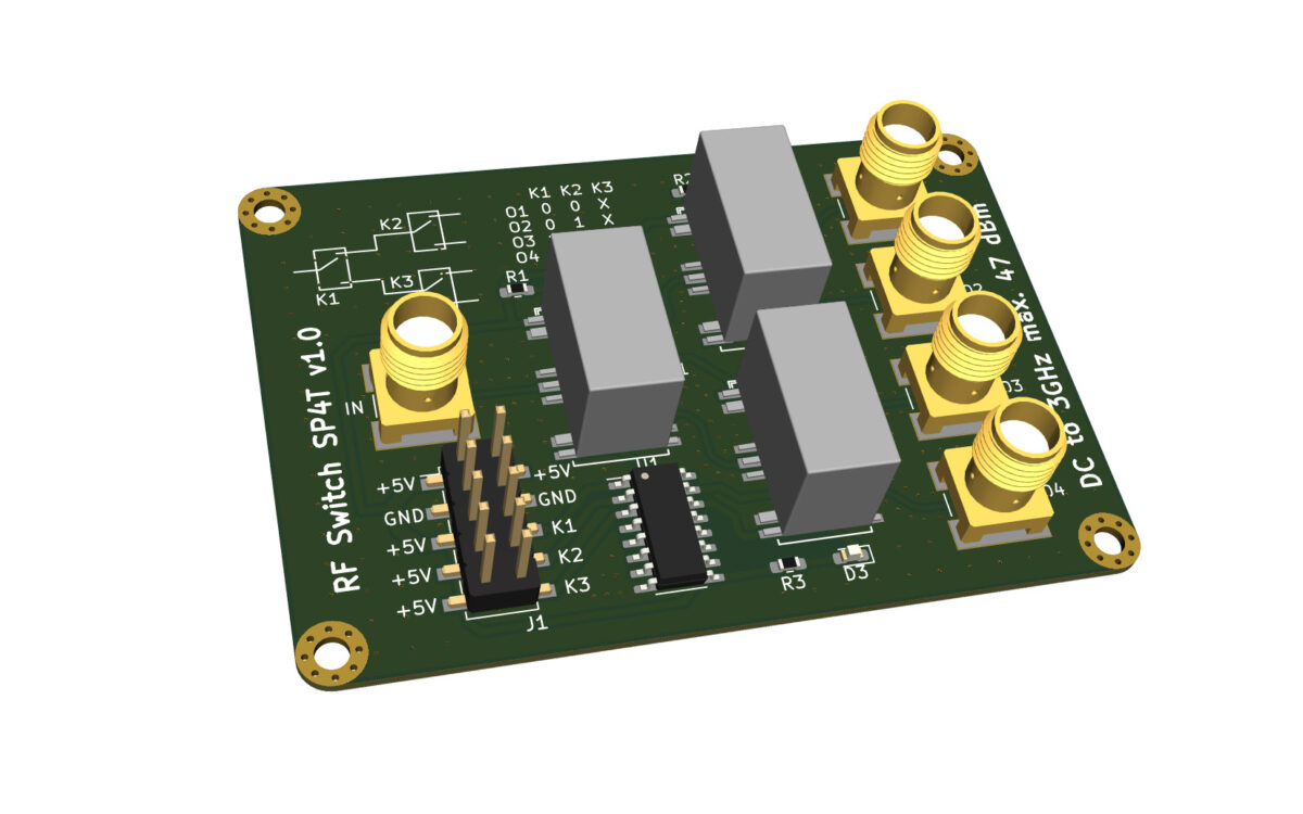
3D view (KiCad model)
Description
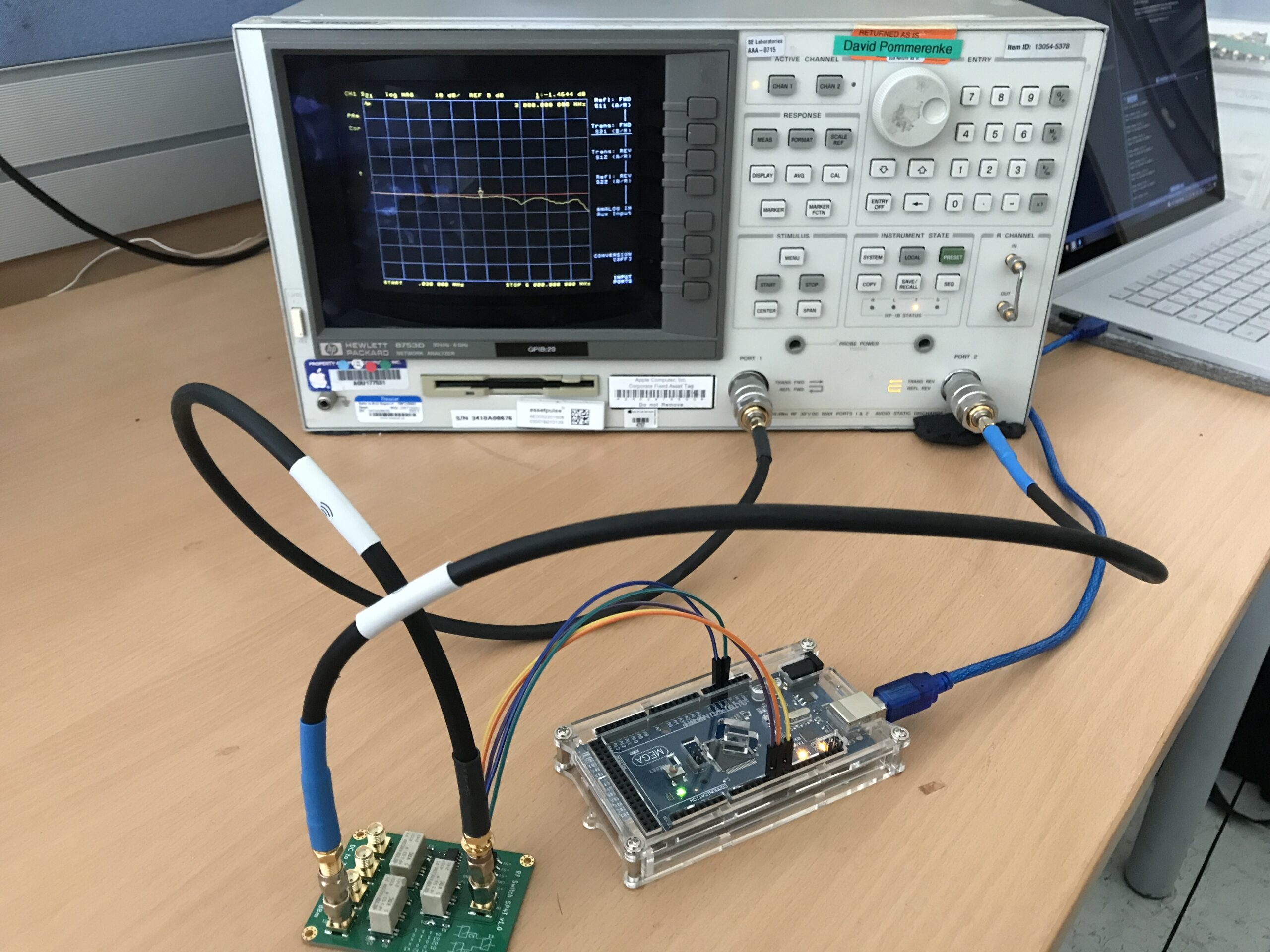
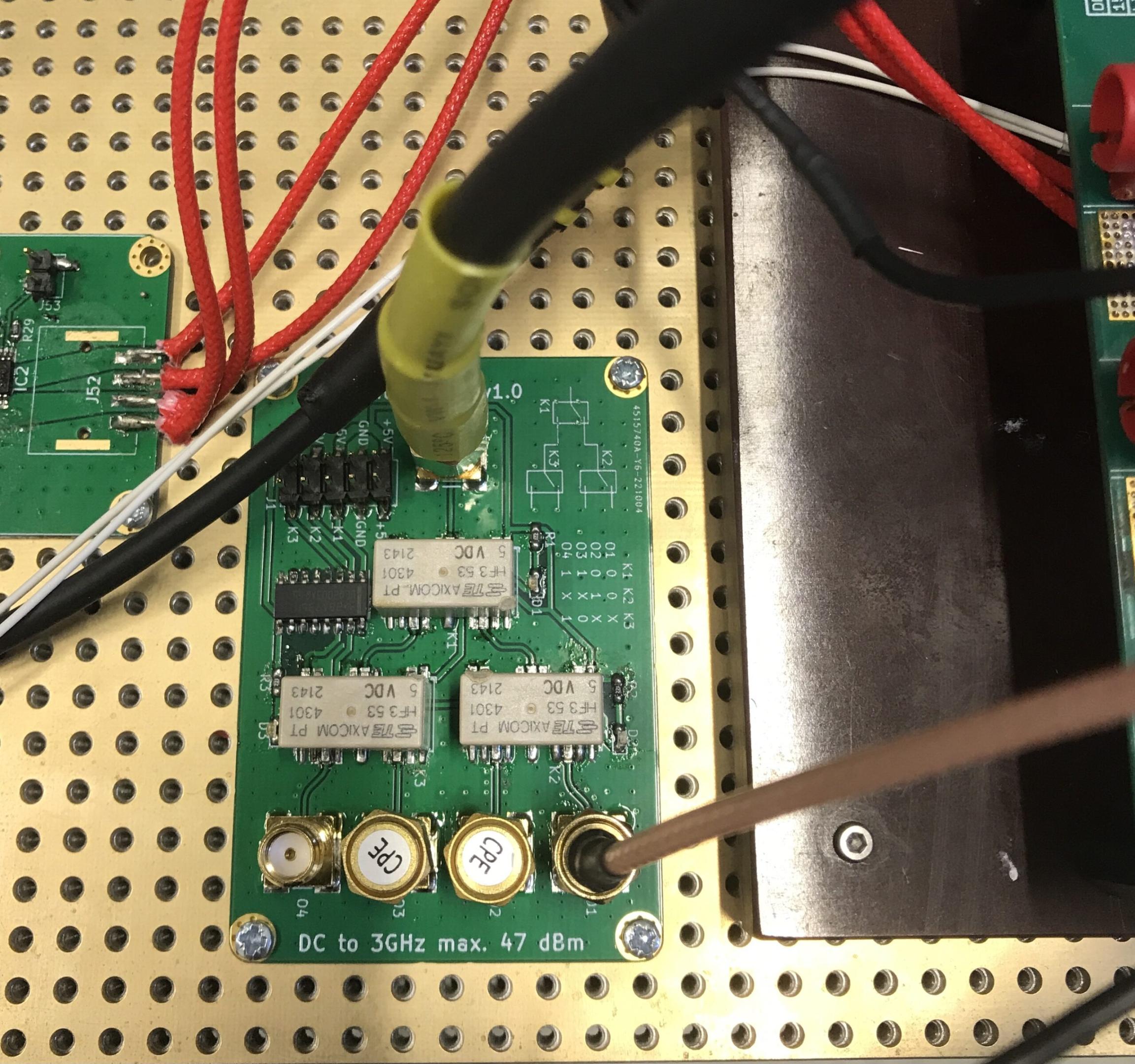
Using three HF3-53 type RF relays, an input signal (DC to 3 GHz) with a power of up to 47 dBm can be switched to four different outputs. Next to each RF relay a small LED is placed to quickly indicate the switching position of the relay. A TTL compatible Darlington transistor array IC with an integrated freewheeling diode is used to control the relay. By using jumper connectors (shorts) on the respective header pins K1, K2 and K3 to 5 V, the relays can also be controlled manually. It is a 4-layer PCB using the JLC7628 stackup with fenced 50 Ω coplanar waveguides routed on the top layer. The bottom layer is left blank in order to make good connection with the ground metal plate which acts as common mounting plate for all the modules. At 3 GHz, the signal gets damped around 1.47 dB. This damping can be compensated by increasing the value of amplification of the signal at the amplifier. All four channels show approximately the same damping characteristic over frequency. The picture below shows the assembled switch being tested with an VNA as well as the connections to the microcontroller and the serial interface to the controlling PC.
Pictures