
People often have structurally separate lawns around their house with a big main lawn and a smaller one. Purchasing another 160-180 Euro charging station, which also acts as signal generator for the wire loop, seems to not be worth for the small second area.
Introducing the Signalbox v1

With this small signal generator, a second, separate wire loop can be placed in another area. The robotic lawnmower works for the time previously set (15 min, 30 min, 45 min, 60 min or 75 min) and then switches off and stops moving.
The robotic lawnmower has to be physically carried over to the second area and then brought back to the charging station located in the main area afterwards.
3D Model (PCB made in KiCad, Box made in Solidworks)
Features
- inexpensive compared to a second charging station
- very easy to set up, just connect the perimeter wire and the power adapter
- protected against splash water and dirt
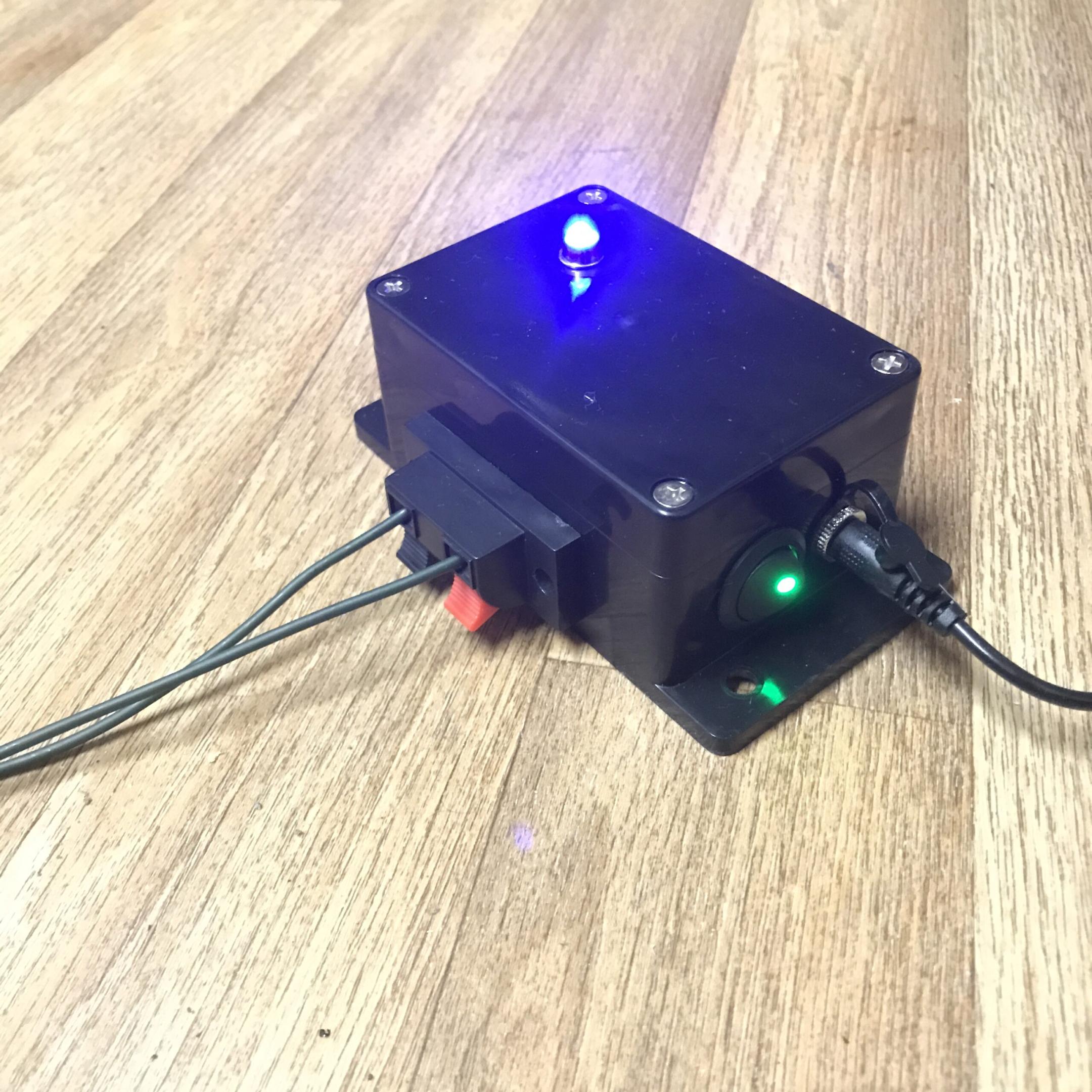
- illuminated on/off switch
- reverse polarity protection
- LED signal indicator
- five different time settings (15, 30, 45, 60 or 75 minutes)
- robustly designed electronics with high quality brand components
- and probably a few more things but I’m not a marketing guy and this is not an online shop
Circuit diagram, code and technical description
Input voltage is 12V. The 5V for the ATtiny13A are provided by an LM7805 linear regulator. Diode D1 is for reverse polarity protection, a p-channel MOSFET could also be used for this but here the small voltage drop is not critical since there comes a linear voltage regulator afterwards anyway. An LED is permanently turned on when the signal is fed onto the wire and blinks once the pre-programmed time is over.
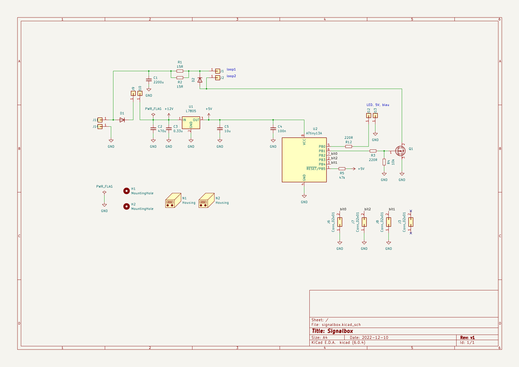
Two parallel 10W 15 Ohm load resistors are connected via the perimeter wire to an n-channel MOSFET in low side configuration. The MOSFET gets switched on and off repeatedly to generate the required signal. Between the solder pads for the fence wire, an appropriate flyback diode is placed (voltage requirement is about two times the nominal voltage, current requirement is the current through the wire which is smaller than 12V/7.5 Ohm = 1.6A). Time selection is done with 3 jumpers (3 bits) connected to Ports 2,3 and 4. Each time value is associated with a certain combination of the bits. Internal pull-up is activated and the jumper pulls the respective port low.
Determining the required signal for the fence wire
Some wire was connected to the original charging station to close the loop. After some measurements and looking at their PCB it was clear, that the circuit uses an n-channel MOSFET as lowside switch. The oscilloscope probe was then tapped at the terminal which is connected to the drain of said MOSFET to receive clear switching flanks.

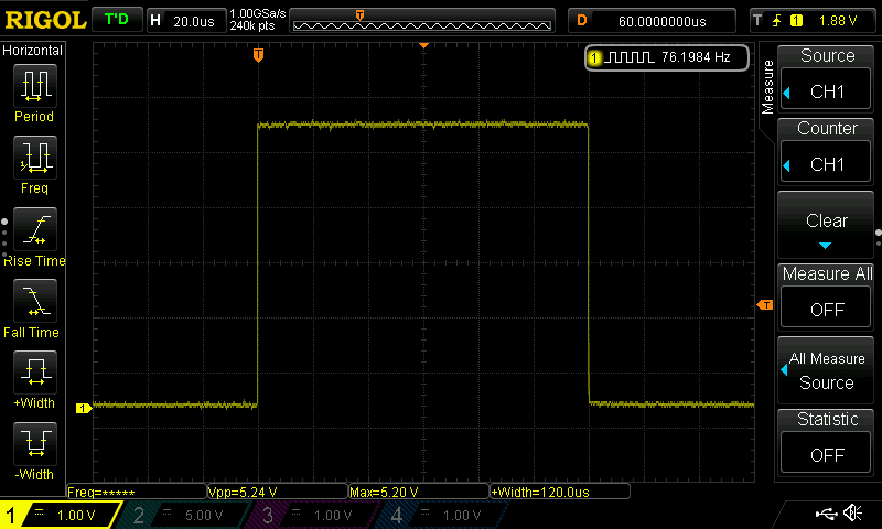
The screenshot below shown the signal on the drain connection of the internal MOSFET.

The frequency of the square wave signal is 76Hz, the shown pulse has a width of around 120 microseconds.

The signal on the gate of the MOSFET must therefore be inverted to the shown signal above. It will be a 75Hz square wave which is 120 microseconds high and 13040 microseconds low, duty cycle is approximately 1%.
I’m using 12V for the signalbox, the original charge station uses 24V. Since the robot detects the magnetic field emitted by the perimeter wire, only the current through the wire is decisive and not the voltage.
Code
An ATtiny13A is used. Why? Because it was the only available and appropriate AVR chip on mouser at the time.
Programming was done in Microchip Studio. The .hex file was flashed using AVRDUDESS and USBasp programmer. Clock was set to 9.6 MHz with the CKDIV8 fuse bit enabled, therefore 1.2MHz. Fuse configuration : Low: 0x6A and High: 0xFF. Low clock and high prescaler was preferred for coding the timer stuff since the ATtiny13A only offers 8 bit timing registers. I was actually a bit concerned that the amount of onboard flash memory of the ATtiny13A wouldn’t be sufficient, but it turned out to be enough. The code below uses about 46% of the available 1kB flash and 6% of the 64 byte data RAM.
|
1 2 3 4 5 6 7 8 9 10 11 12 13 14 15 16 17 18 19 20 21 22 23 24 25 26 27 28 29 30 31 32 33 34 35 36 37 38 39 40 41 42 43 44 45 46 47 48 49 50 51 52 53 54 55 56 57 58 59 60 61 62 63 64 65 66 67 68 69 70 71 72 73 74 75 76 77 78 79 80 81 82 83 84 85 86 87 88 89 90 91 92 93 94 95 96 97 98 99 100 101 102 103 104 105 106 107 108 109 110 111 112 113 114 115 116 |
#ifndef F_CPU #define F_CPU 1200000UL #endif volatile unsigned int counter = 0, elapsed_minutes = 0; #include <avr/io.h> #include <util/delay.h> #include <avr/interrupt.h> #include <stdbool.h> void port_setup (void) { DDRB |= (1<<PB0); //PB0 led output, lights up when signal is given to wire DDRB |= (1<<PB1); //PB1 Mosfet output, 76 Hz PORTB &= ~(1<<PB0); PORTB &= ~(1<<PB1); //user sets timer through jumper (short to GND) on those 3 ports DDRB &= ~(1 << PB4); // bit0 DDRB &= ~(1 << PB3); // bit1 DDRB &= ~(1 << PB2); // bit2 //activate pullups PORTB |= (1 << PB4); // bit0 PORTB |= (1 << PB3); // bit1 PORTB |= (1 << PB2); // bit2 } int get_minutes(void) { int minutes; //read user jumper configuration bool bit0 = (PINB & (1 << PINB2)); bool bit1 = (PINB & (1 << PINB4)); bool bit2 = (PINB & (1 << PINB3)); //set how long signal is applied to wire if (bit2 && bit1 && !bit0) { minutes = 15; // jumper only on bit0 } else if (bit2 && !bit1 && bit0) { minutes = 30; // jumper only on bit 1 } else if (bit2 && !bit1 && !bit0) { minutes = 45; // jumper on bit 1 and bit 0 } else if (!bit2 && bit1 && bit0) { minutes = 60; // jumper only on bit 2 } else if (!bit2 && bit1 && !bit0) { minutes = 75; // jumper on bit2 and bit 1 } else { minutes = 15; // default } return minutes; } void timer_setup(void) { // set prescaler to 1024 TCCR0B |= (1 << CS02) | (1 << CS00); } void disable(void) { //disable timer and interrupt OV flag TIMSK0 &= ~(1<<TOIE0); TCCR0B &= ~(1 << CS02); TCCR0B &= ~(1 << CS00); } void generate_signal(void) { // signal int microseconds_high = 106; // adjusted to get a 76Hz square wave with 120us t_high in the end int microseconds_low = 11780; int signal_duration_minutes = get_minutes(); // LED ON, permanent ON means that signal is currently fed into wire PORTB |= (1<<PB0); while (elapsed_minutes < signal_duration_minutes){ PORTB |= (1<<PB1); _delay_us(microseconds_high); PORTB &= ~(1<<PB1); _delay_us(microseconds_low); } } ISR(TIM0_OVF_vect) { // called 4.6 times per second, 1200000/1024/256 (8 bit register) // theoretically 4.6*60 = 276 counts for 1 minute // but found out that rather a value of 270 is equal to 1 min if (++counter > 270) { elapsed_minutes++; counter = 0; //reset the counter } } int main(void) { sei(); TIMSK0 |= (1<<TOIE0); // enable OV interrupt flag port_setup(); timer_setup(); generate_signal(); disable(); // optional while (1) { // blinking signals that programmed time is over // blinks till device is turned off by physical power switch PORTB |= (1<<PB0); _delay_ms(500); PORTB &= ~(1<<PB0); _delay_ms(500); } return 0; } |
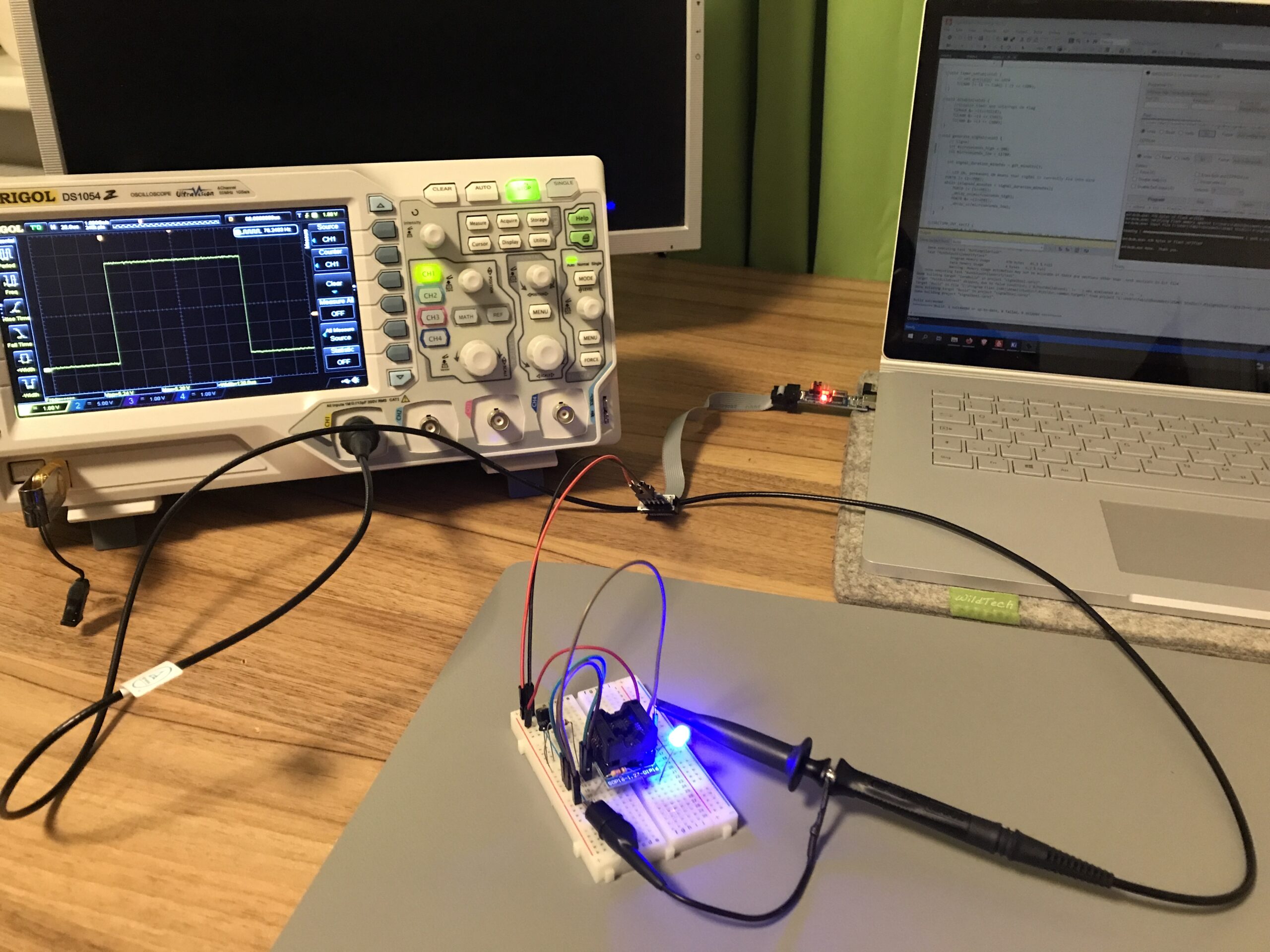
Testing the code/debugging
A first simulation was done in SimulIDE, it’s like Proteus with fewer functions but free and often completely sufficient.

Then the code was tested on an actual ATtiny13A with an oscilloscope measuring the generated signal.
The LOW time of the signal was then adjusted until the 76Hz and 120us high-time were achieved, because with the calculated values (13040 microseconds for LOW) only a 69Hz square wave signal was generated.
However… flashing the program onto another chip results in a different frequency again. The internal RC oscillator is not that accurate nor very temperature stable. I had a total of 10 Attiny13A available and I flashed every one of them with the same code and measured the resulting frequency. Results are shown in the table below.
| Attiny13A # | Frequency in Hz |
| 1 | 78.9 |
| 2 | 76.1 |
| 3 | 74.8 |
| 4 | 71,1 |
| 5 | 74.0 |
| 6 | 76.8 |
| 7 | 75.9 |
| 8 | 73.6 |
| 9 | 76.8 |
| 10 | 72.03 |

Furthermore, I exposed some chips to the heat of my hot air gun and some ice spray while monitoring the frequency. It varied around 5 Hz in both directions.
Now the thing is that the Attiny13A does not support an external crystal resonator but requires a whole oscillator circuit (expensive) if you want to feed an external clock. I originally figured that the internal RC oscillator might as well do the job, but I’m not so sure any more. The second revision (if one ever comes) will probably feature an external oscillator. Since all pins of the ATtiny13A, including the CLKI pin, are already occupied, the status LED will probably be moved and connected to the drain side of the MOSFET to free a port. That way, the LED lights up (around 99% duty cycle) as long as the signal is live and goes dark when the preset time is over, instead of blinking when the time is up. Not much of a loss. And a DIP switch will be used instead of the jumpers. I believe the robotic lawn mower can deal with a slight variation of the frequency and it does not really matter if he works one minute more or less. As a workaround, I manually calibrated the two devices I built so far with a stop watch.
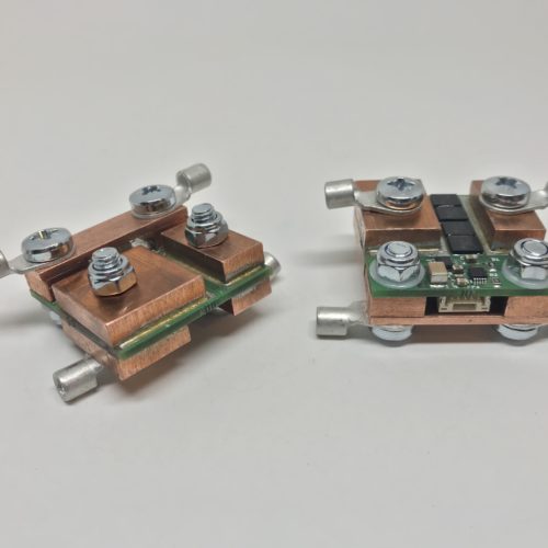
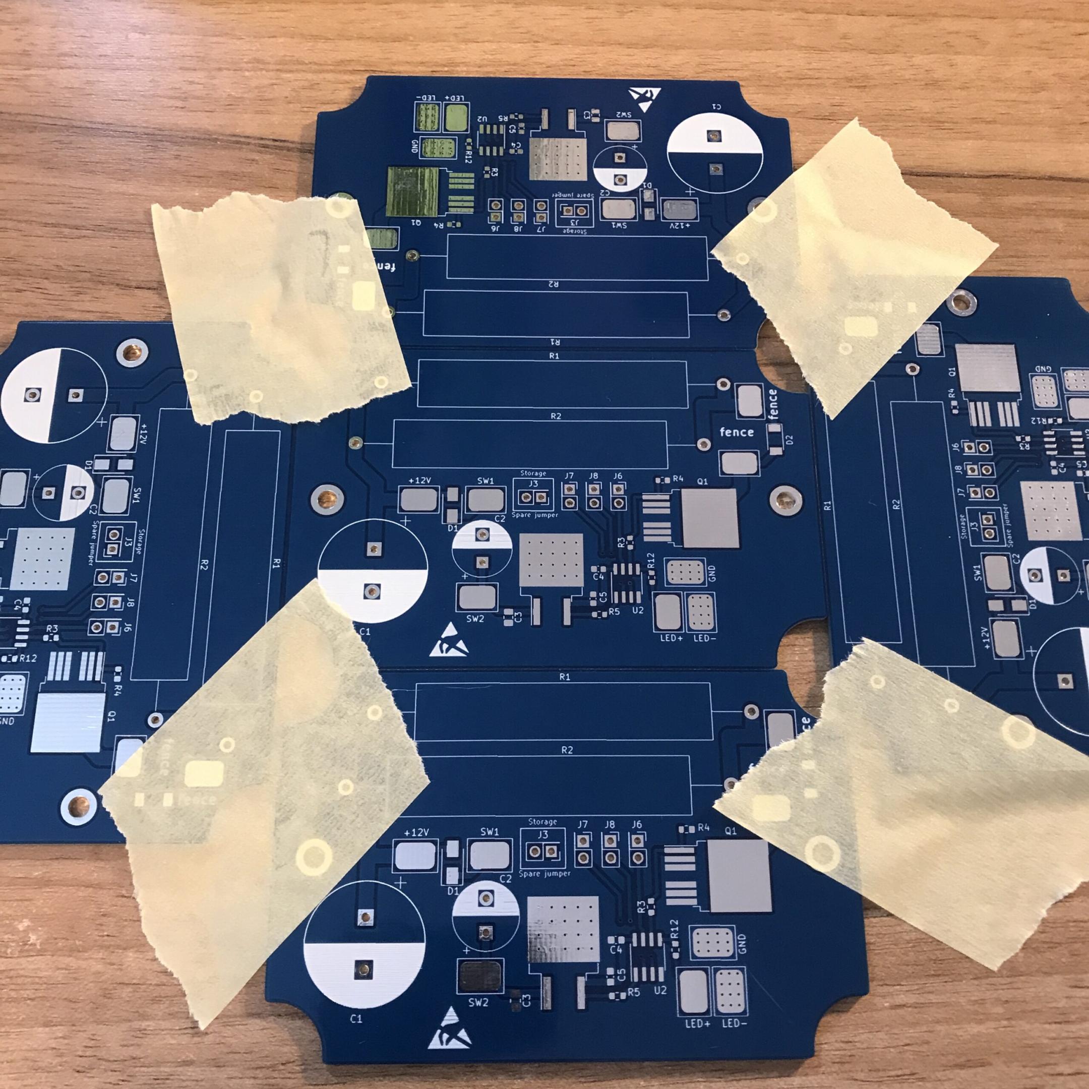
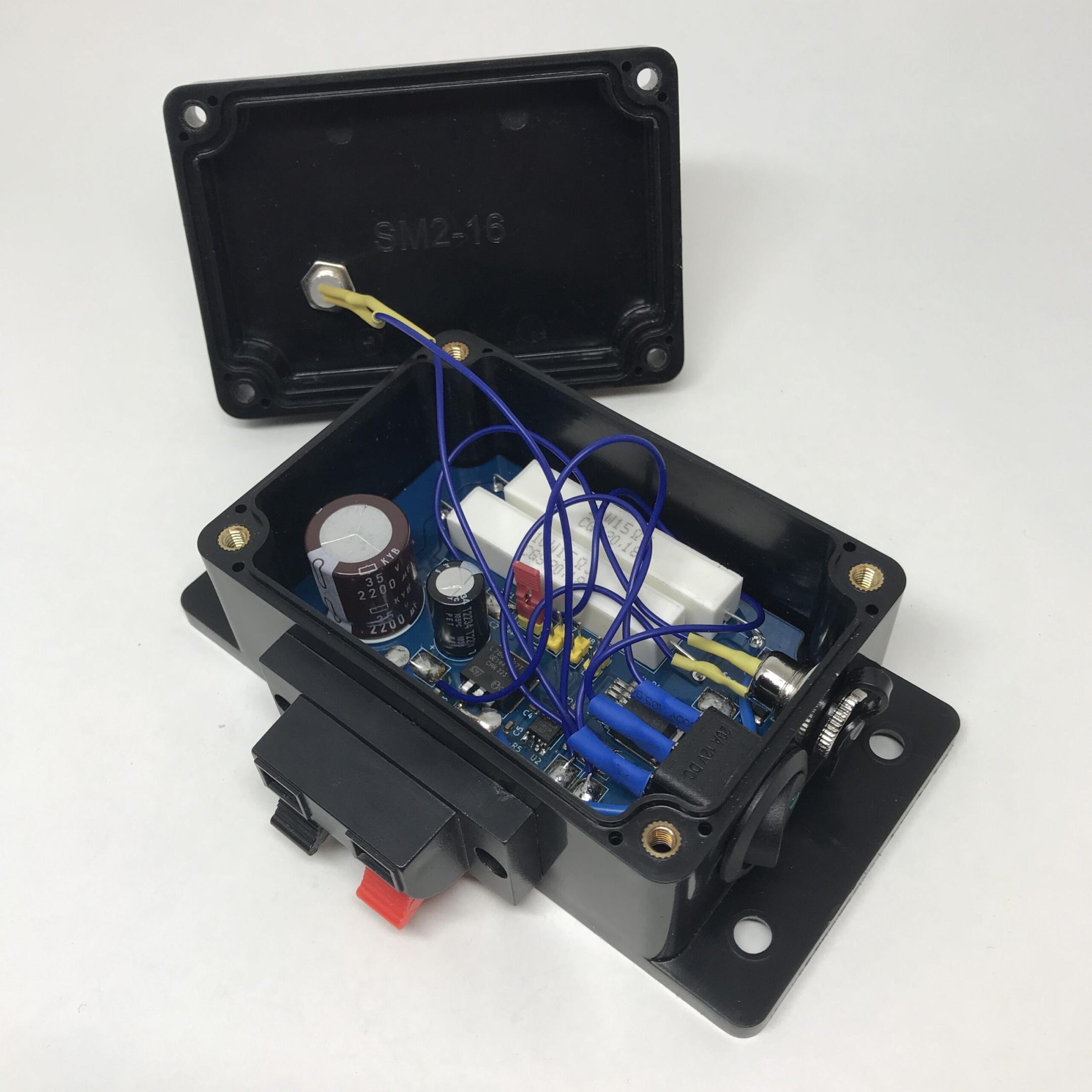
PCB Assembly and box preparation

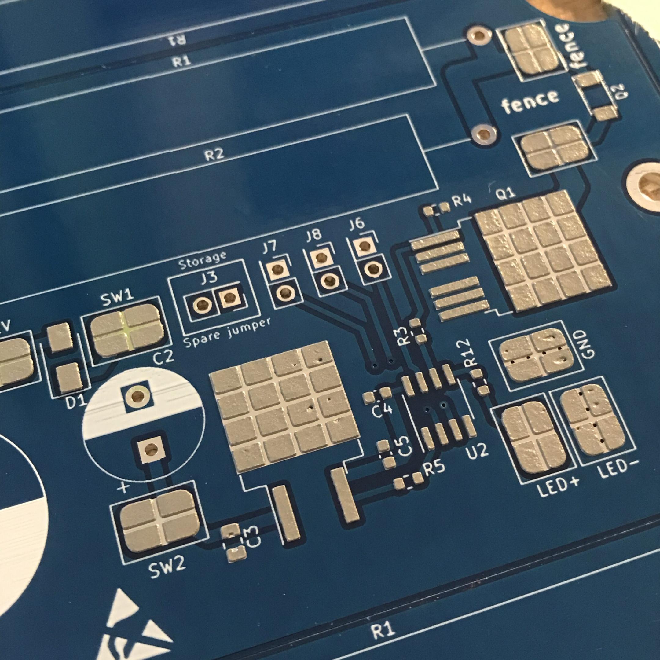

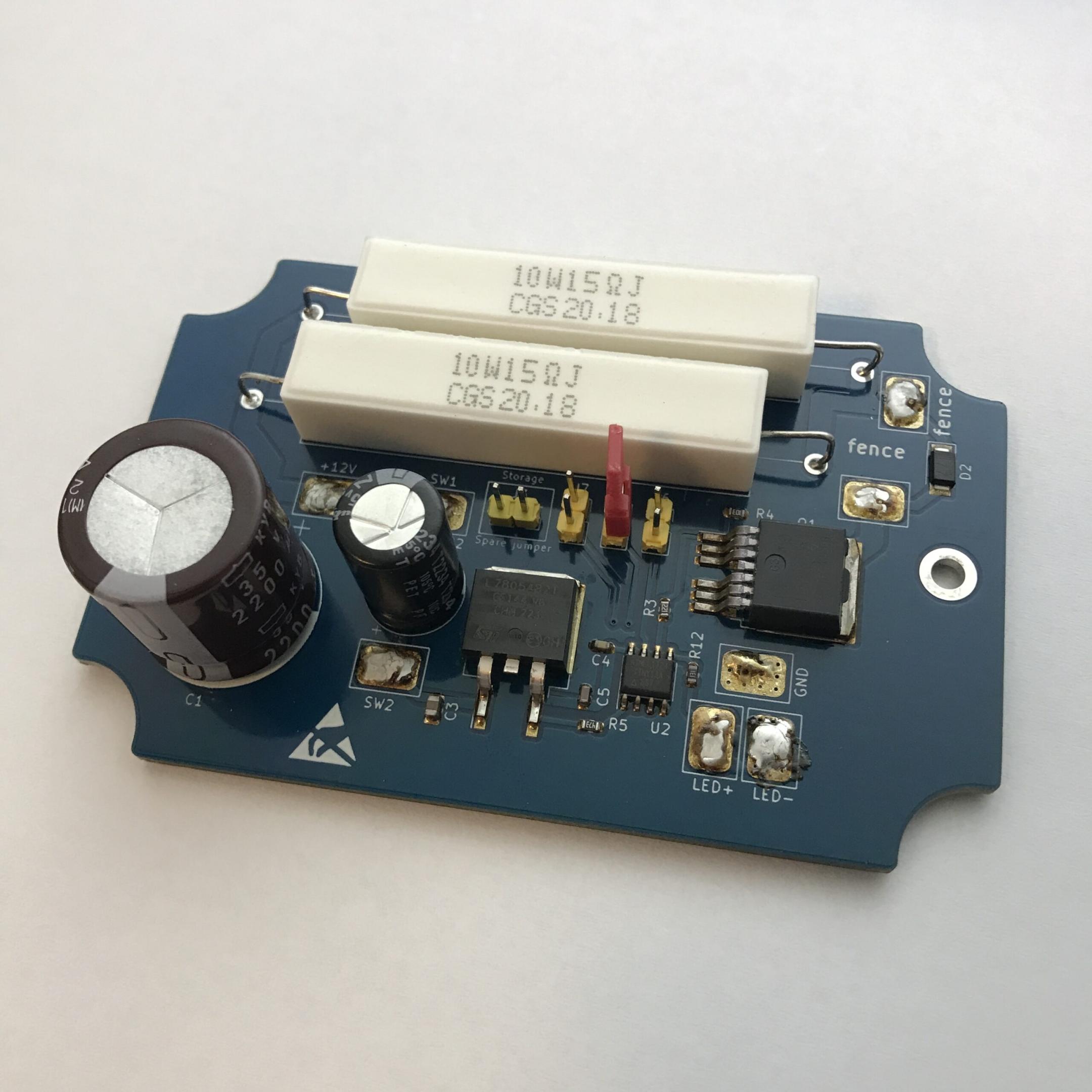
Depending on which of the yellow pin headers are shorted with the red jumper connector, the working time of the lawnmower can be set (15, 30, 45, 60 or 75 minutes).
Box
With the provided drawings of the box and my caliper, I drew a 3D model of the case in Solidworks. After the PCB was routed I printed it 1:1 on paper and cut if out to check if it fits inside the box and if the mounting holes are correctly placed before ordering the PCBs.

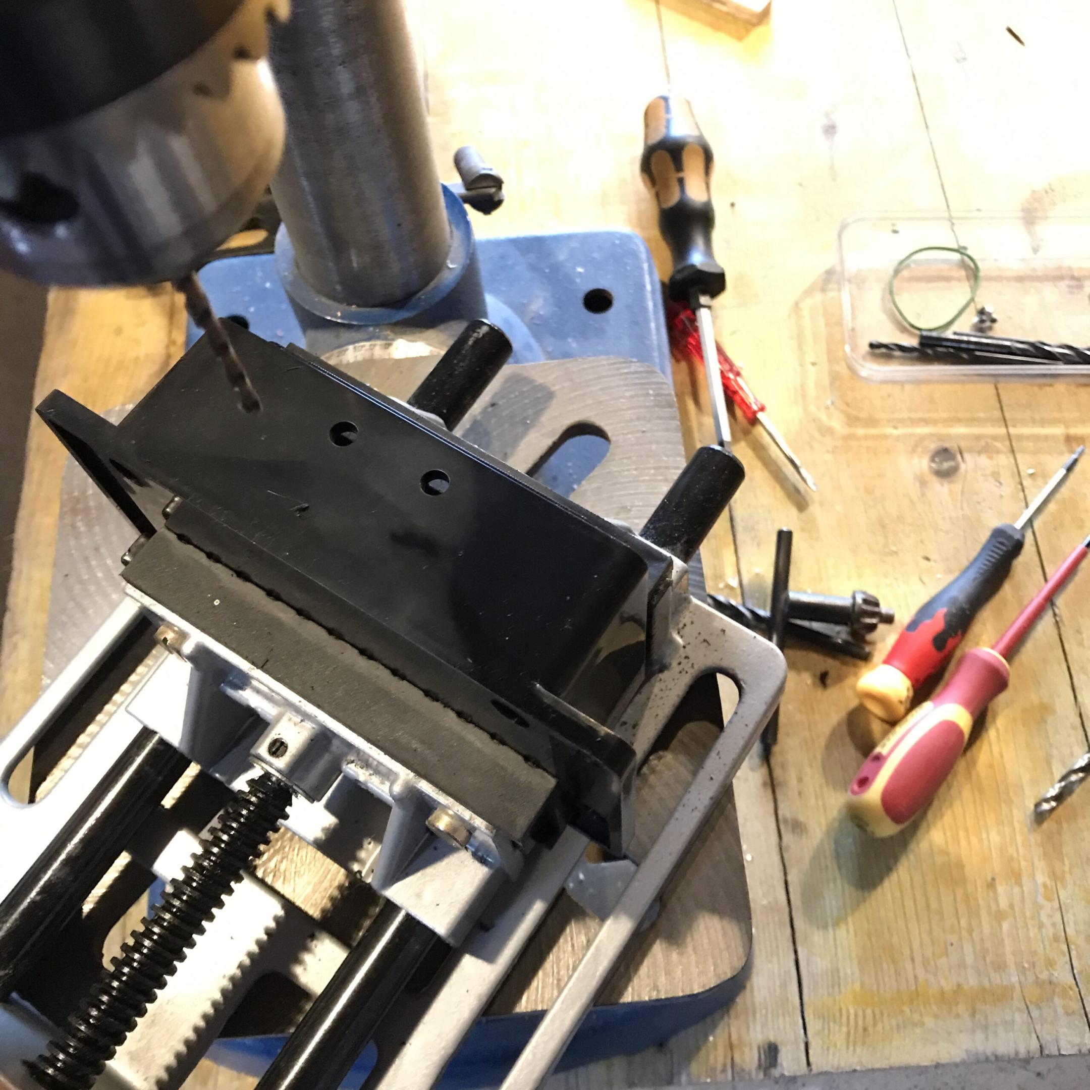
The more tricky part was to make sure the parts mounted into the case did not collide with other components inside. After a good placement of the external components was found, drill points were marked with paper templates.

Completely assembled device:


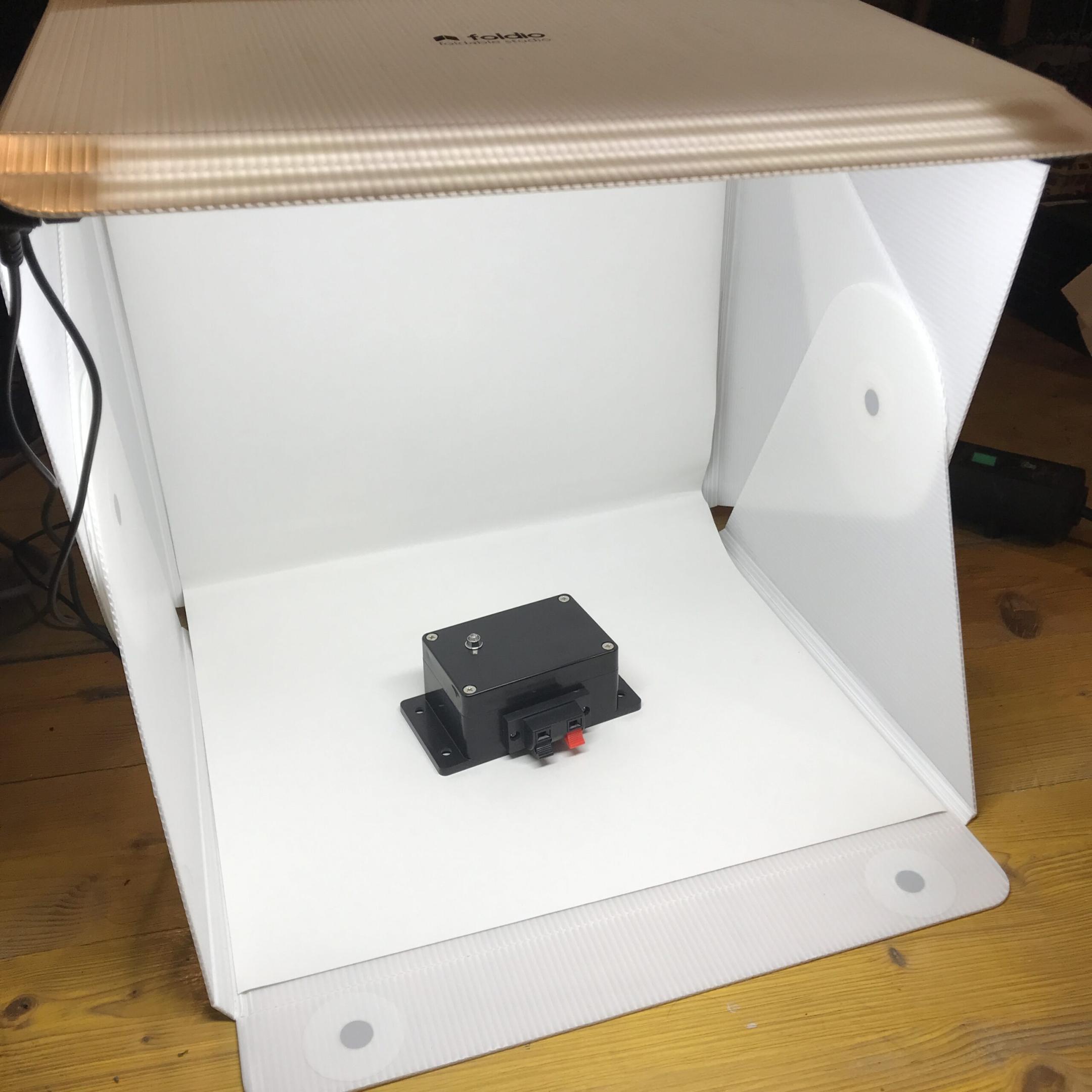
Testing


Initial outdoor test
Hugo (my Landroid LX790 robotic lawnmower) was then finally introduced to the signalbox.
Since there was a decent amount of snow in the garden, I set up an alternative area.

Indoor test
The video below demonstrates what happens when the set time has been reached. The status LED will start to blink, the lawnmower will turn around itself for a few seconds, then throw an E1 error code (missing wire signal) and remains still.
Improvements for future revisions
- using an external oscillator instead of the internal one
- maybe replacing the pin headers with a DIP switch (although more expensive)
- changing orientation of some solderpads
- replacing the ceramic cap on the output side of the 7805 linear voltage regulator with an aluminium electrolytic capacitor of the same value (reason: higher ESR for more stability in the feedback loop), although it seems to work fine with the ceramic capacitor
The picture below already shows the updated version with an 10 MHz external oscillator (X1) and a DIP switch instead of the jumpers. The status LED was previously connected to the CLKI port and since no other port was free any more, it was moved and is now also switched by the MOSFET. So as long as the signal is fed into the fence wire, the LED lights up, once the timer is up, the LED goes dark.