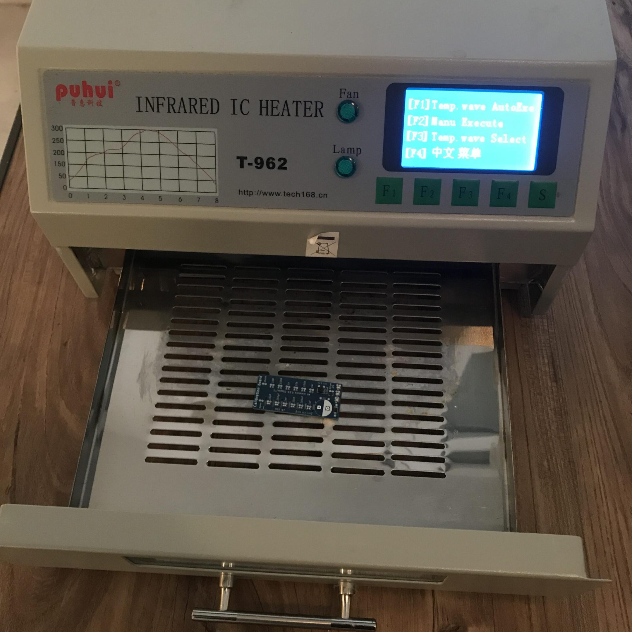

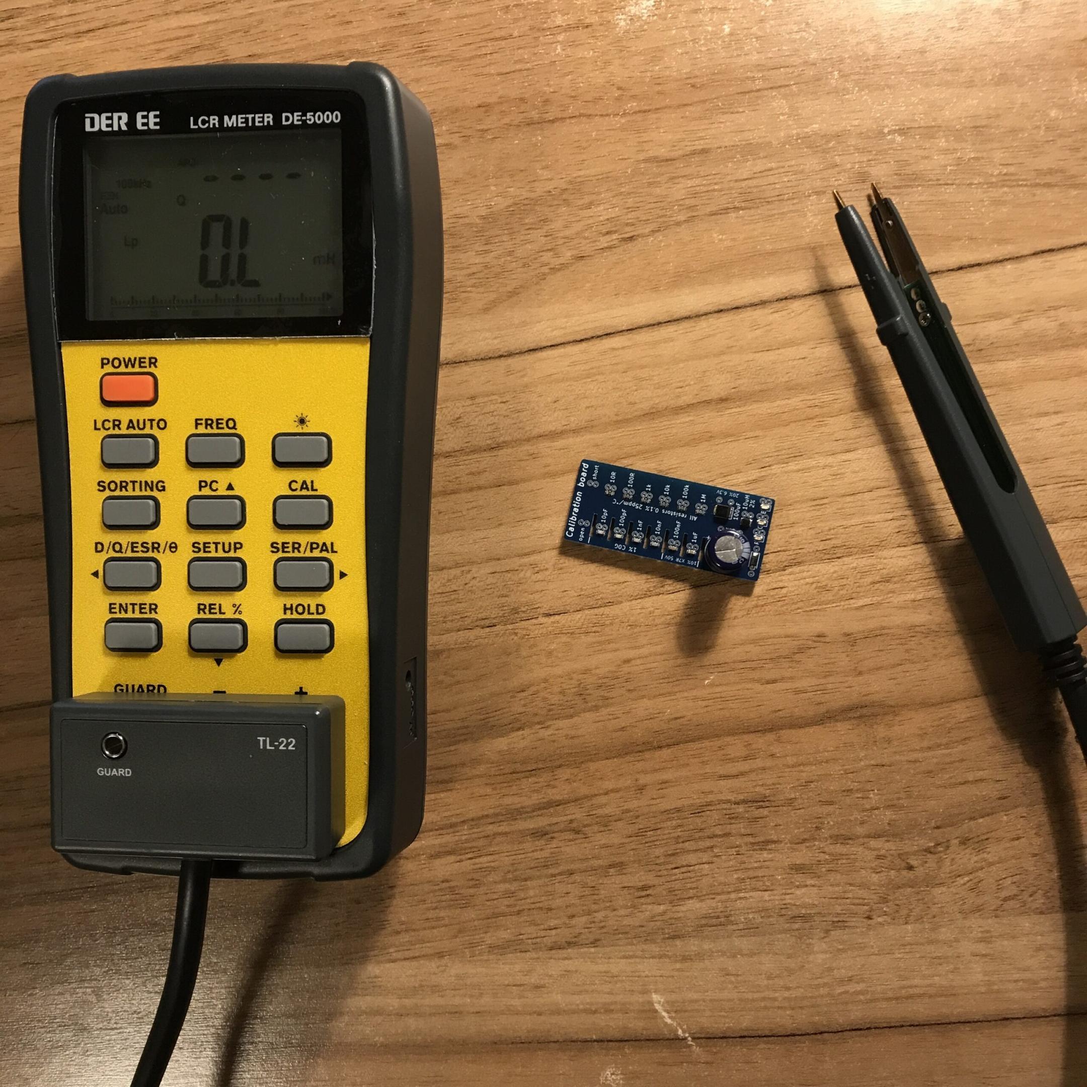
This is a board to test the capabilities of LCR meters, like my DER-EE DE-5000 LCR-meter.

3D model (KiCad)
Components
Capacitors:
- 10 pF, 100 pF, 1 nF, 10 nF MLCC in 0603 size with 1% tolerance and C0G dielectric
- 100 nF, 1 uF MLCC in 0603 size with 10% tolerance and X7R dielectric (50VDC rating to minimize DC bias effect)
- 1000 uF electrolytic capacitor, 20% tolerance
- 100 uF tantalum polymer capacitor, also 20% tolerance
Resistors:
- 10R, 100R, 1k, 10k, 100k, 1M in 0603 size with 0.1% tolerance and 25ppm/°C
Inductor:
- 10 uH inductor in 0805 size with 2% tolerance
Diodes:
- One standard diode and a red, green and blue LED in 0603 size (bottom right)
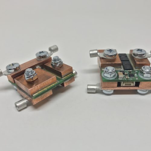
Calibration can be performed with the short and open contacts. Open calibration is useful when measuring capacitors, short calibration is useful when measuring resistors.
Slots between the capacitors help to reduce parasitic capacitance because the  of air is factor 4-5 lower than the of FR4.

Measurements with DER-EE DE-5000 LCR-meter
| Capacitor values | 100 Hz | 1 kHz | 10 kHz | 100 kHz |
| 10 pF | 5 | 10,9 | 10,9 | 11,06 |
| 100 pF | 101 | 101,4 | 101,44 | 101,45 |
| 1000 pF (1 nF) | 1003 | 1006,5 | 1005,9 | 1006,2 |
| 10 nF | 10,119 | 10,113 | 10,112 | 10,109 |
| 100 nF | 102,95 | 101,61 | 100,38 | 97,42 |
| 1000 nF | 1044,4 | 973,9 | 842,7 | 801,8 |
| 100 uF (tantal) | 101,16 | 98,37 | 96,5 | O.L |
| 1000 uF (electrolytic) | 1015.3 | 896 | O.L | O.L |
There is also a 120Hz setting for the measuring frequency which I skipped. Why is there a 100Hz/120Hz setting? The frequency on the output side of a full-wave bridge rectifier (where the big chonky electrolytic capacitors are placed) is double the frequency value on the input side. Well the EU has a 50Hz AC grid, the USA has a 60Hz grid, therefore the 100Hz/120Hz option.
| Resistor values in Ohm | fmeas = 10 kHz |
| 10 | 9,957 |
| 100 | 99,87 |
| 1k | 0,9995 |
| 10k | 9,996 |
| 100k | 99,92 |
| 1M | 0,9982 |
| Inductor value | 100 Hz | 1 kHz | 10 kHz | 100 kHz |
| 10 uH | 13 | 10,6 | 11,17 | 11,096 |
The forward voltage measurements were carried out with a Voltcraft VC265 multimeter. According to the manual, the maximum applied voltage in the diode test function is 1.48V. The red LED lights up very weakly, the green and blue one obviously stay dark.
| Device | Measured forward voltage in V |
| Standard diode | 0,561 |
| LED red | – |
| LED green | – |
| LED blue | – |
Part numbers of components used
| Capacitors | Manufacturer part number |
| 10 pF | GCM1885C2A100FA16J |
| 100 pF | GCM1885C2A101FA16D |
| 1 nF | GCM1885C2A102FA16D |
| 10 nF | GRM1885C1H103JA01J |
| 100 nF | UMK107AB7105KA-T |
| 1 uF | UMK107AB7105KA-T |
| 100 uF Tantal | TCJB107M006R0055 |
| 1000 uF Electrolytic | ECA-1CM102B |
| Resistors | Manufacturer part number |
| 10 | CRT0603-BY-10R0ELF |
| 100 | RT0603BRD07100RL |
| 1k | RT0603BRD131KL |
| 10k | RT0603BRD1010KL |
| 100k | RT0603BRD07100KL |
| 1M | RT0603BRD071ML |
| Inductor | Manufacturer part number |
| 10 uH | AISC-0805F-100G-T |
| Diodes | Manufacturer part number |
| General Purpose Diode | BAV16W_R1_00001 |
| LED red | 150060RS75000 |
| LED green | 150060GS75000 |
| LED blue | 150060BS75000 |
More pictures