
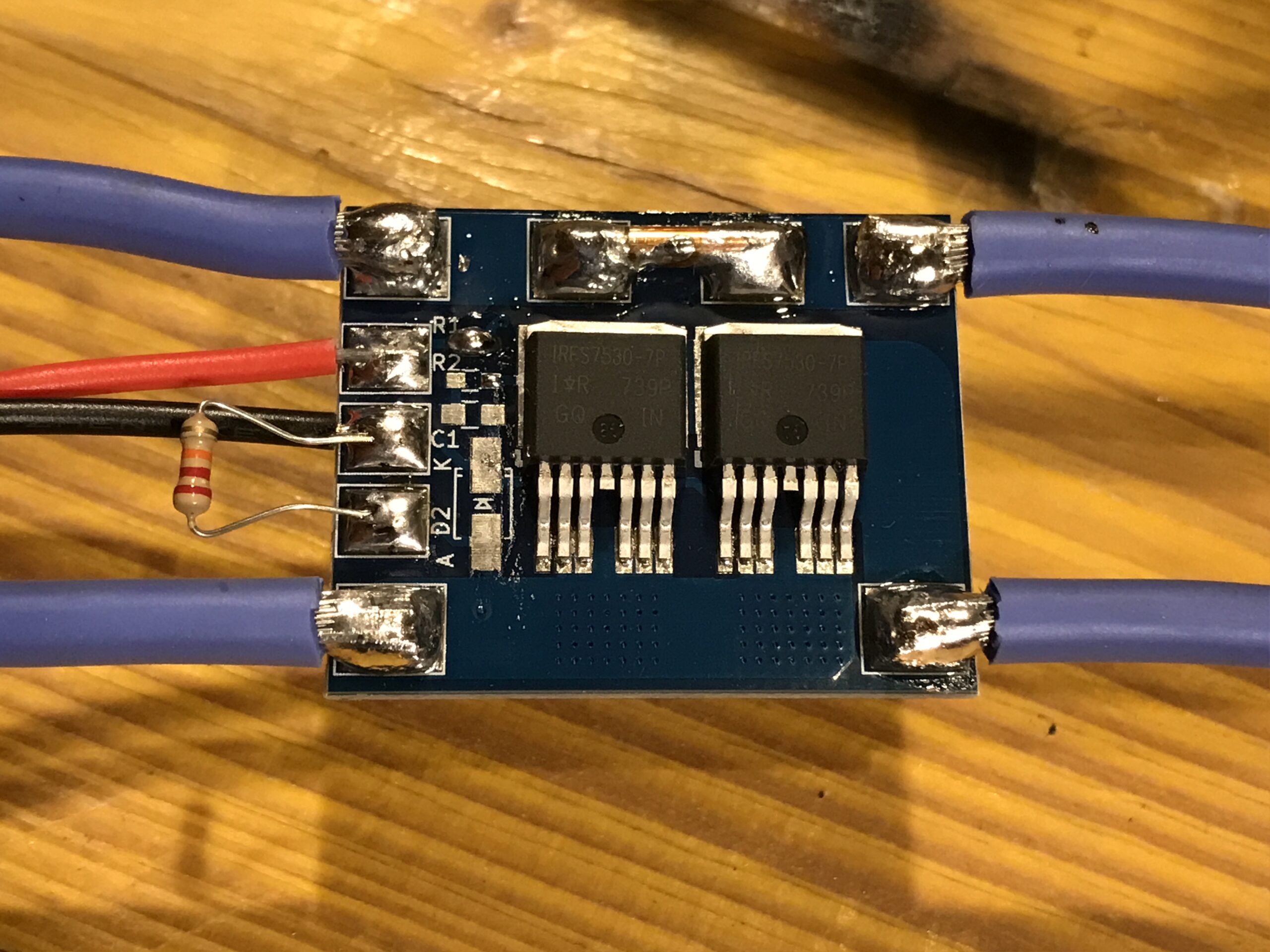
Two MOSFETS are put in parallel in low-side configuration to switch an ohmic load. Load current is set while observing the warming up of the PCB through thermal imaging. Package of the MOSFETS is D2PAK-7, traces are approximately 10mm wide 2oz copper on both top and bottom layer and connected by many vias. The picture below shows the general setup with the switch, wiring, load, current clamp and thermal imaging camera. Not all supply cables were used because it was not planned to increase the current beyond 100A.
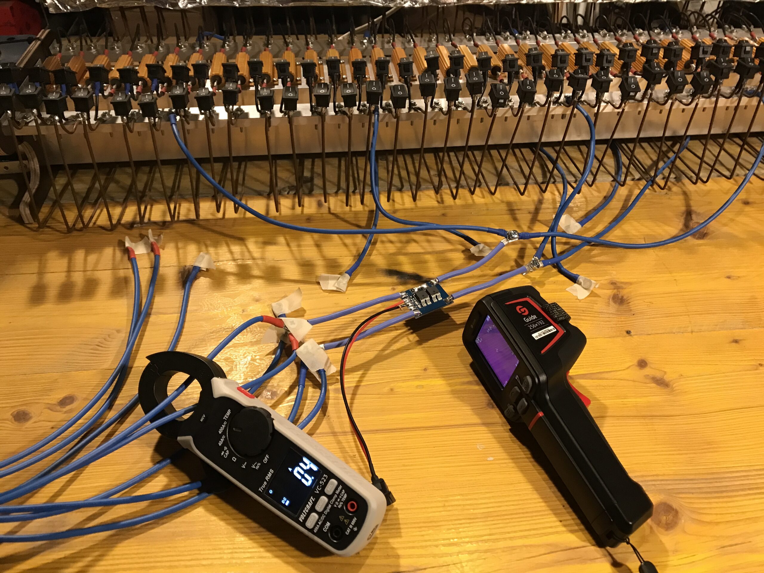
The PSU is connected to the left side of the board with 12V on top left and ground on bottom left. There is also an external SPST switch and a pulldown resistor connected to switch the MOSFETS on and off. The load is connected on the right side, load+ is top right and load- is bottom right.
Video
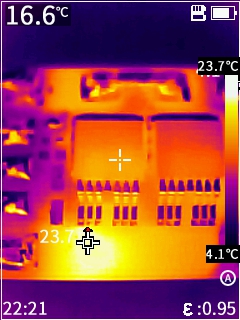
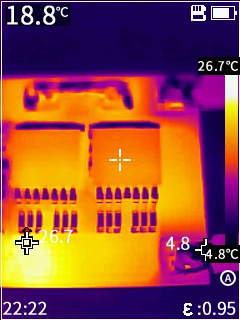
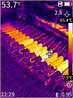
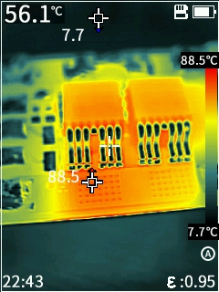
The load current is set to 43.4A while it was filmed through the thermal imaging camera with equipped macro lens how the circuit board heats up. A hotspot can be identified in the bottom left area, where the two current paths meet and many vias are placed. Temperature unit is Celsius. Two cursors continuously locate the hottest and coldest spot in the current view. The temperature at the top left of the display is the temperature at the spot the white cross is aiming at (center of screen).
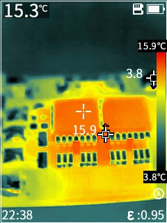
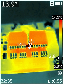
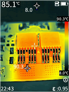
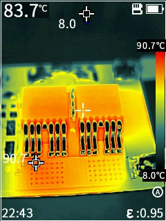
In other experiments, the current was increased up to 80A for a short amount of time and the temperature rise observed.
Ideally half of the total current flows through each MOSFET. With a typical  of 1.15mOhm, each transistor would theoretically dissipate around 0.5W alone, which is not much. There are 0603 resistors with that power dissipation rating. However, the temperature rise is obviously significant.
To determine the complete dissipation power of the switch, the voltage drop between the bottom right and left pads is measured, which is 0.117V, resulting in 5.1W dissipation power and an effective resistance of 2.7mOhm across the switch.
More pictures
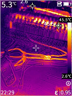
The camera allows to set different color schemes.
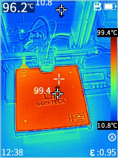
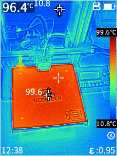
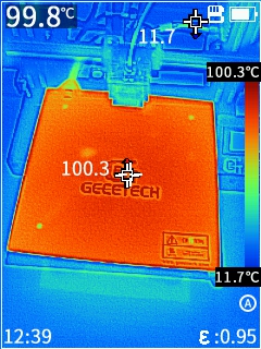
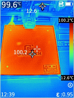
To at least somehow verify the accuracy of the thermal imaging camera, I heated the bed of my 3D printer to 100°C. The resulting pictures are shown below.