
Welcome to this new series of blog posts where we take a closer look at the inner workings of electronic devices!
Introduction
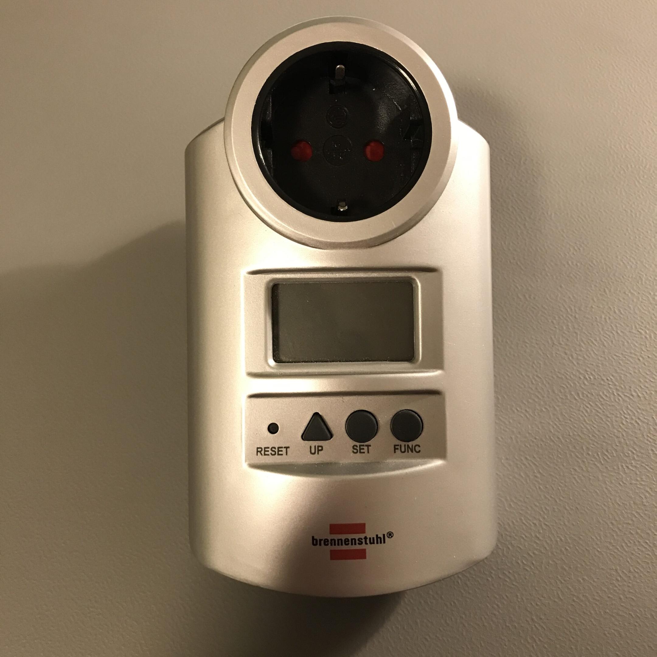
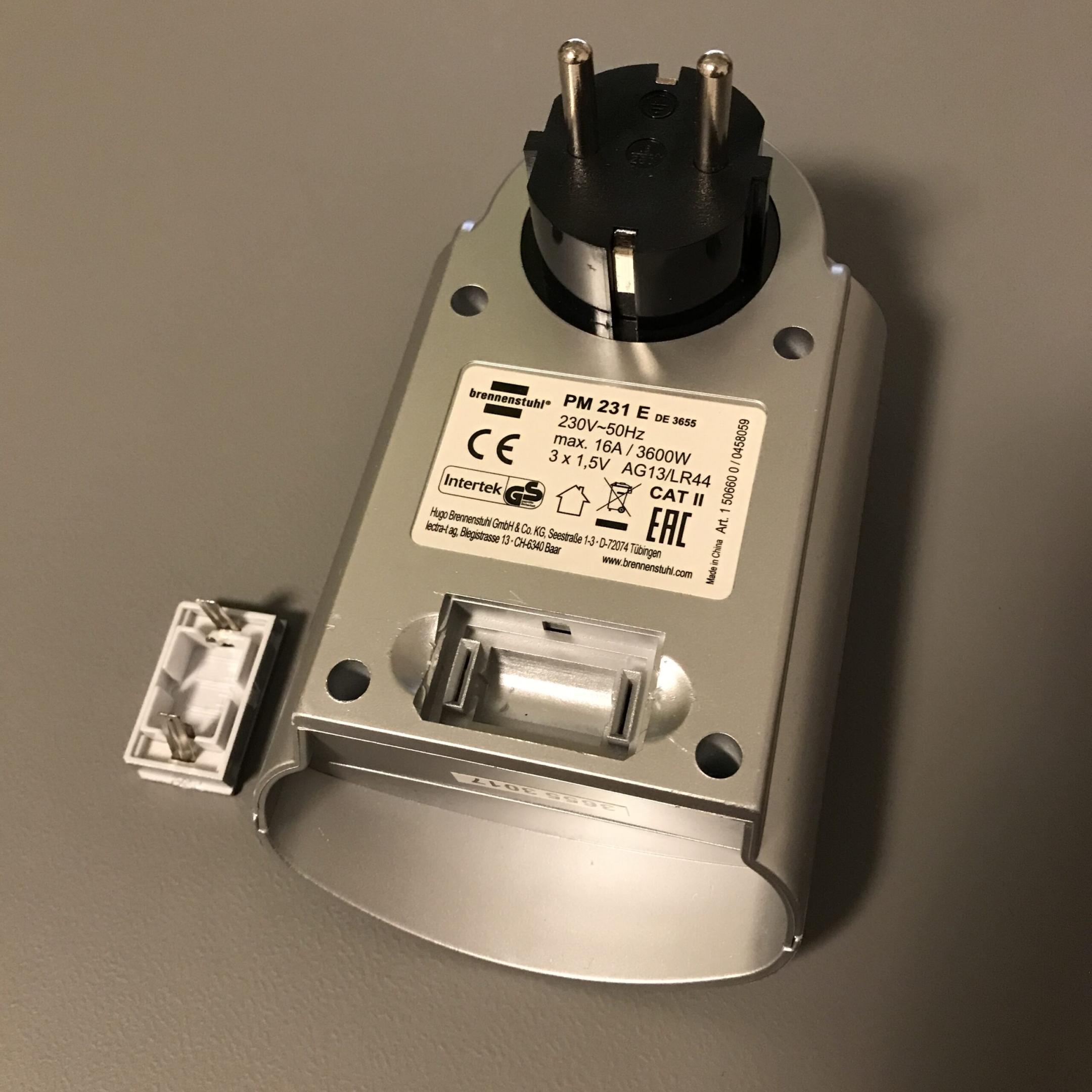
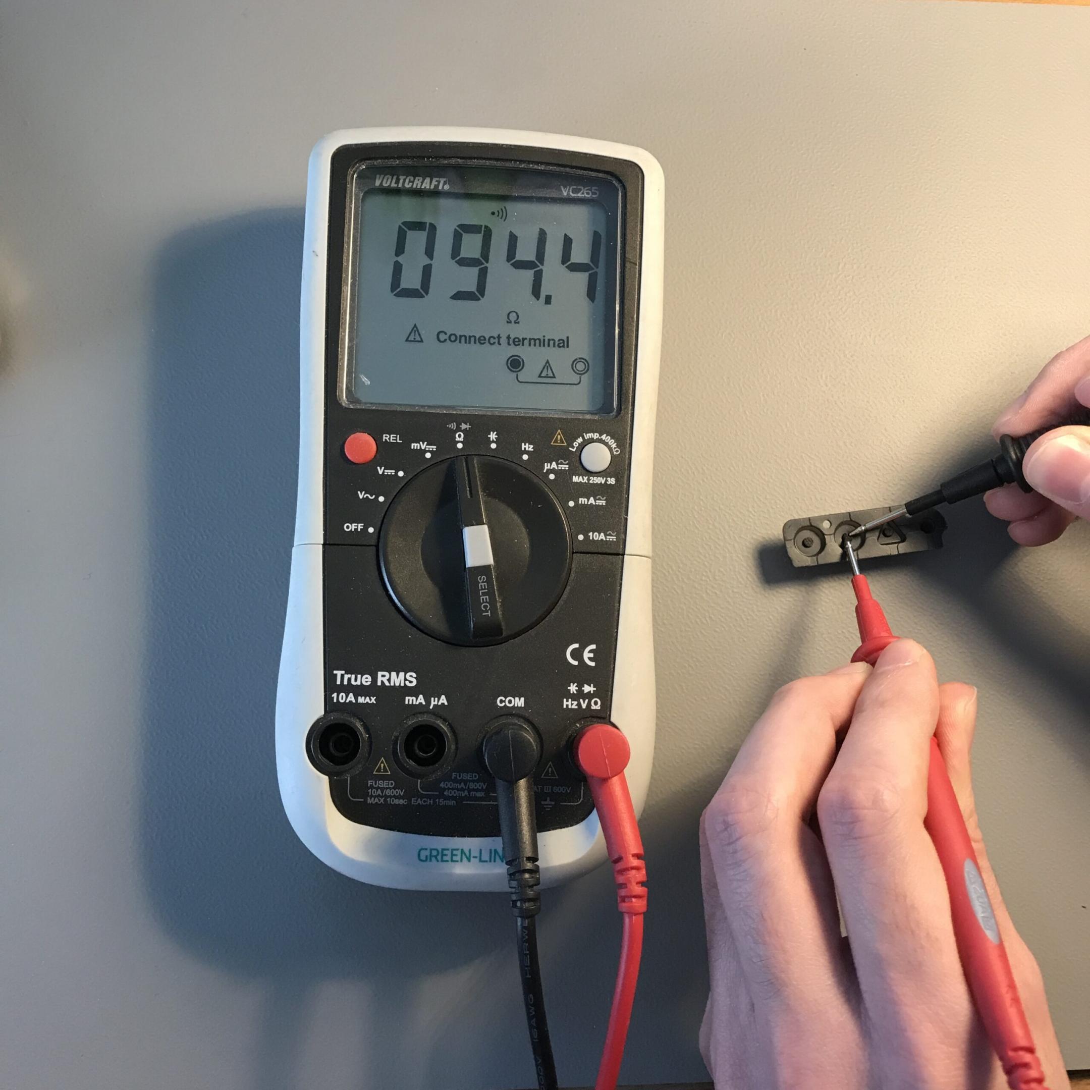
The energy meter has recently stopped showing correct power values. The voltage value is read correctly but the value for the current is doubled most of the time, therefore the power reading is also off about factor 2. Reason enough to open the device up and to see what’s going on.
Lovely tri-wing screw heads.
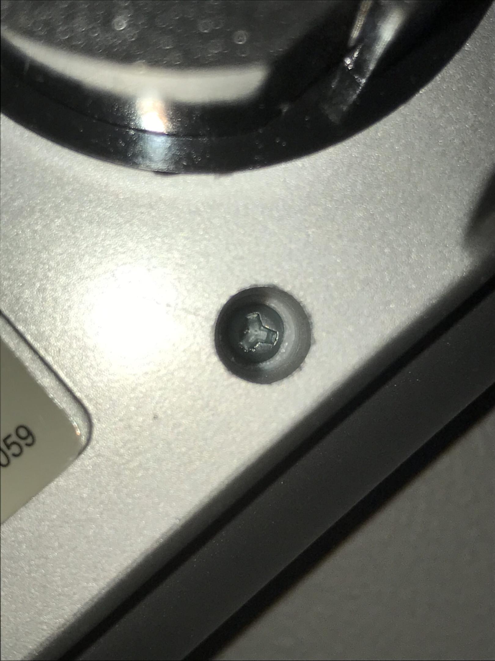
I don’t have such a screwdriver (yet), of course it was a Sunday with all hardware stores closed, so there was only one option left. Drilling.

Finally opened up.
Internals
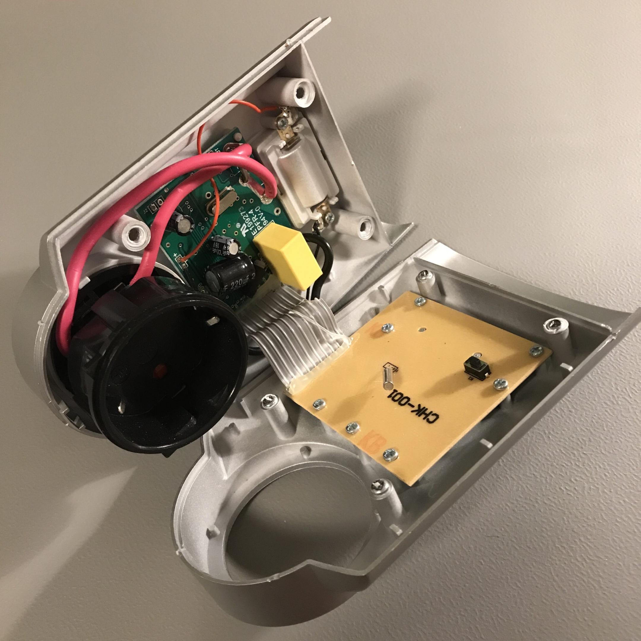
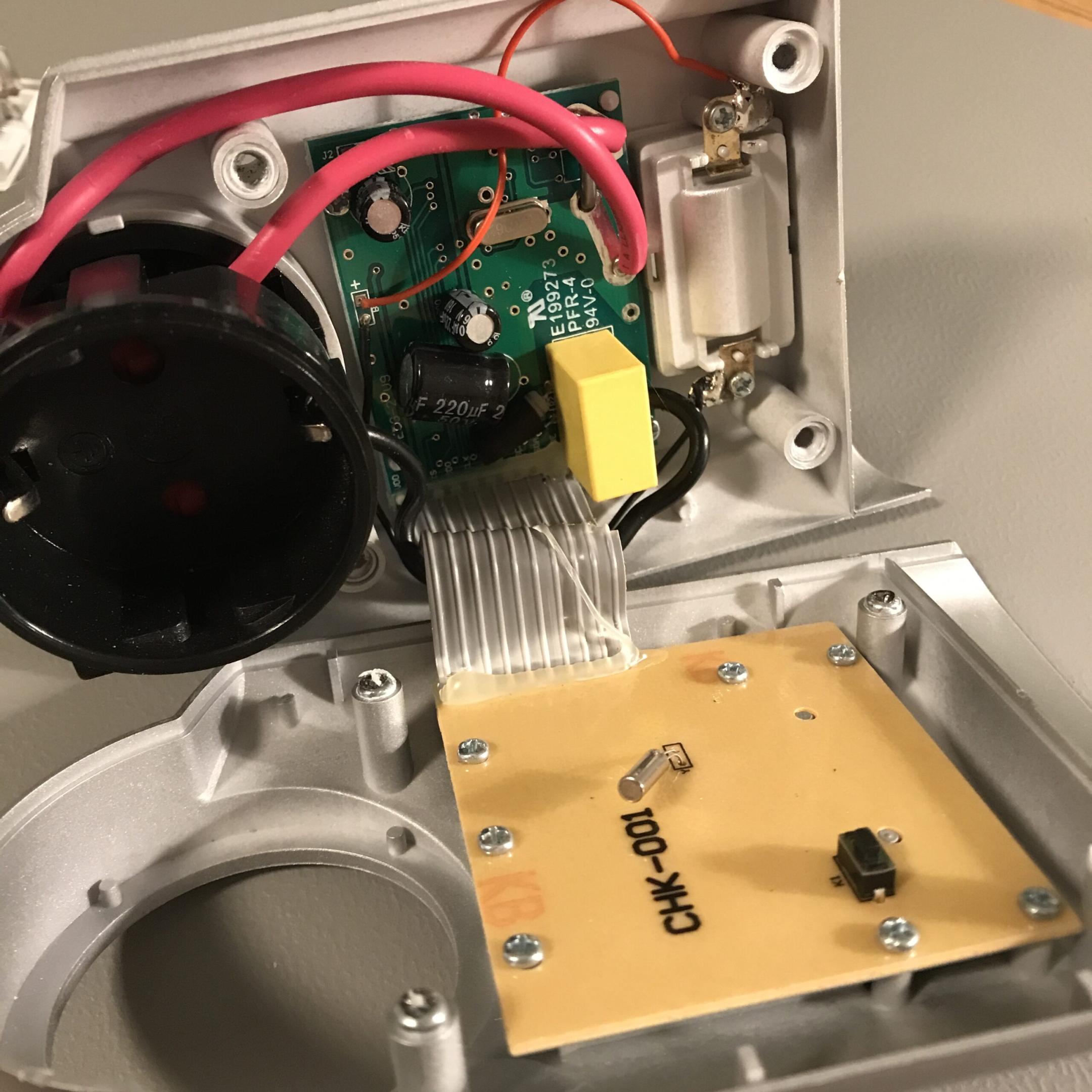
Three electrolytic capacitors are visible, each 220uF capacitance. The voltage rating for the big one is 50V, the two smaller ones are rated for 16V. There is also a 4.096MHz resonator visible. The yellow brick is a film capacitor rated for 0.33uF and 275V, it has a 150Ohm resistor placed next to it covered in shrink tube. There is a thick piece of wire on the PCB between the red wires which is the budget version of a shunt resistor used for current measurement. A ribbon cable connects the green PCB to a second PCB where a crystal and a push button are placed. The button is not accessible from the outside, so it is not for reset purposes.
The display is mounted on the back of the yellowish PCB, according to the silkscreen labelling, I2C is used for communication between the chips.
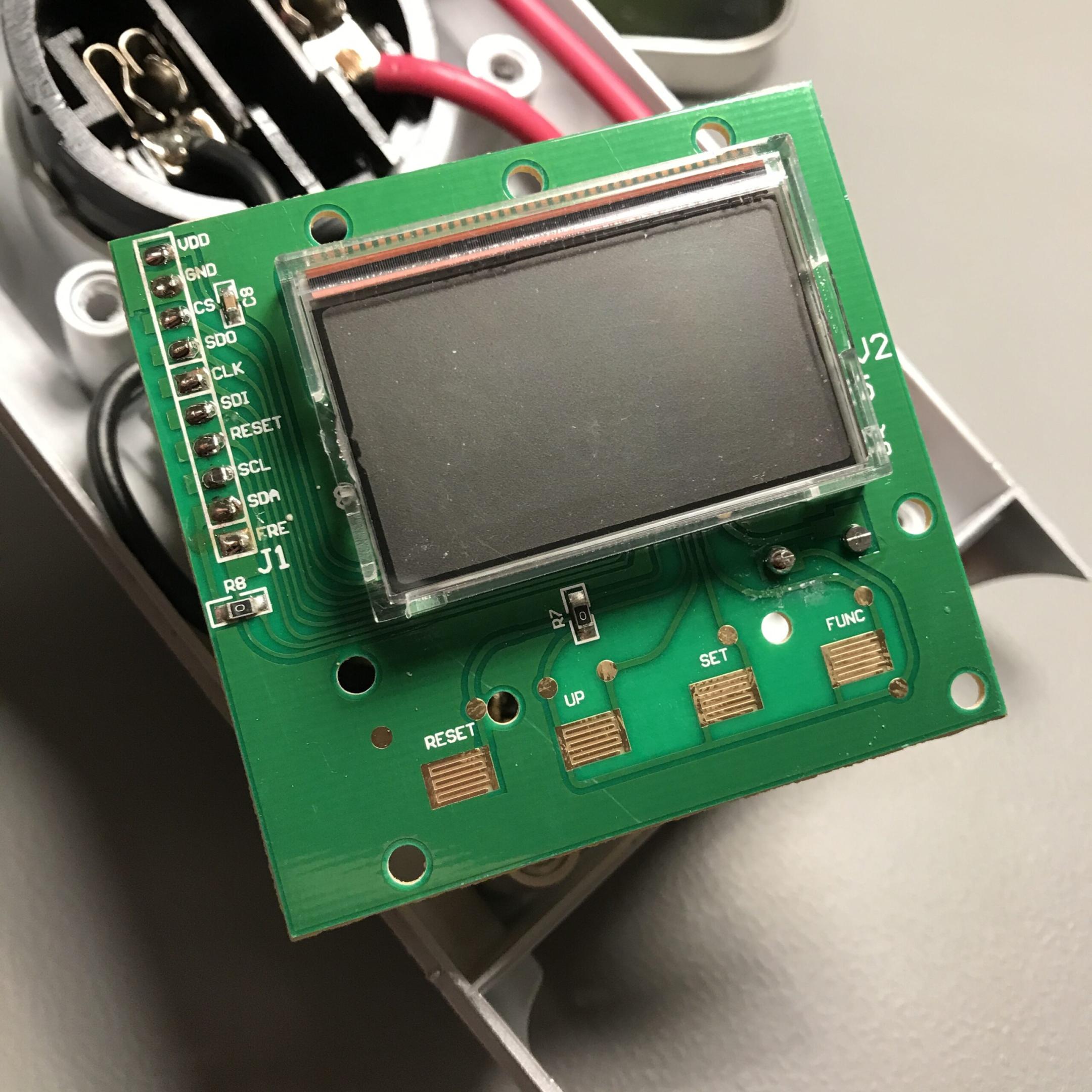
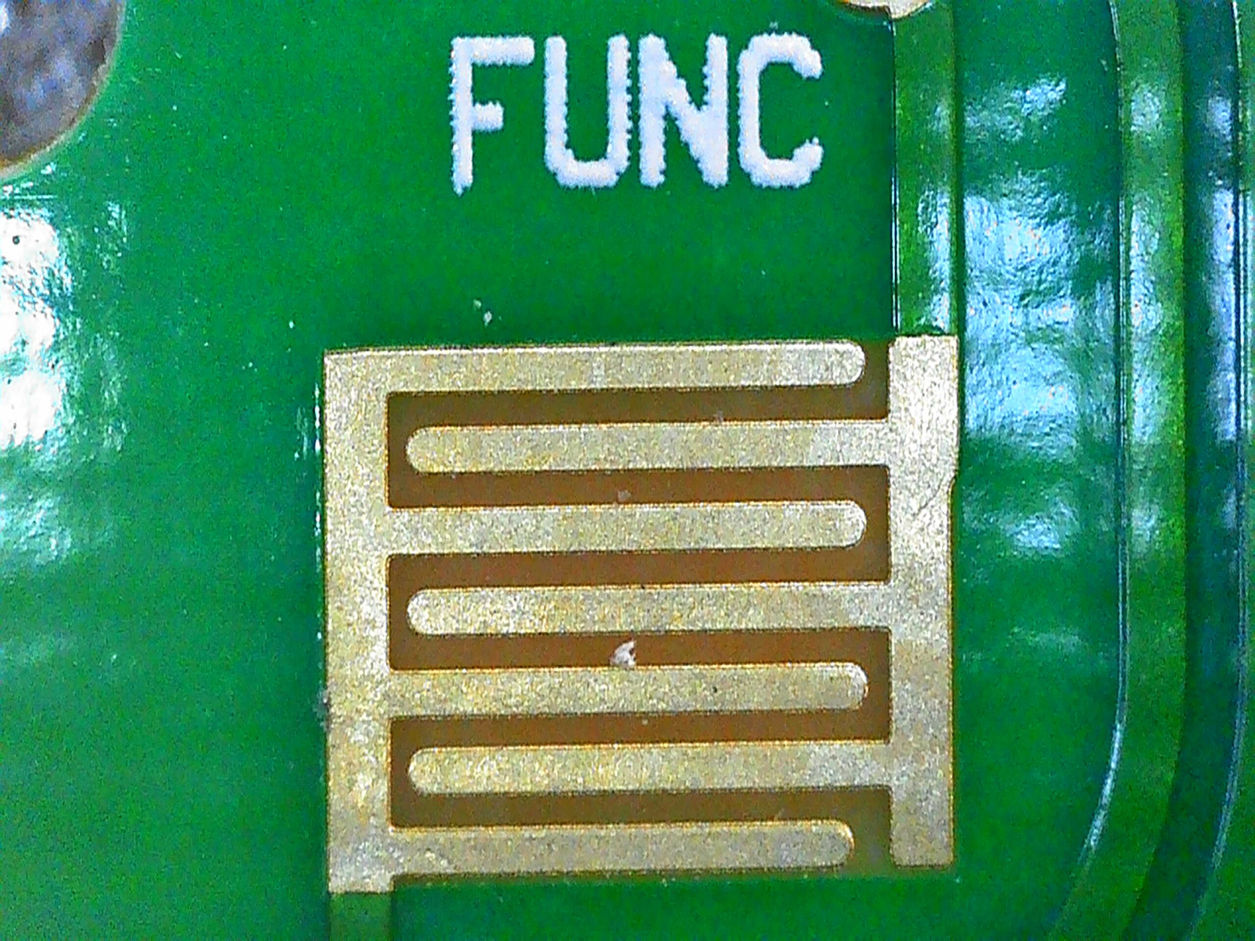
The next thing that catches the eye are the pads labelled RESET, UP, SET and FUNC.
They are interleaved terminals which are not connected. Other names are conductive rubber button PCB pads or conductive PCB buttons.
The rubber button on the back of the keypad is conductive, once it is pressed onto that pad it somewhat shorts it and a user input can be detected, e.g. an input port is pulled low or high that is polled or tied to an ISR.
Now the most of the stuff happens on the green PCB. On the top left (D8) the circuit for the battery terminal input is located (basically just a diode in series for reverse polarity protection). Batteries (three small button cells) are optional and only required if you want to save your settings and measurements when the device gets unplugged from the power outlet.

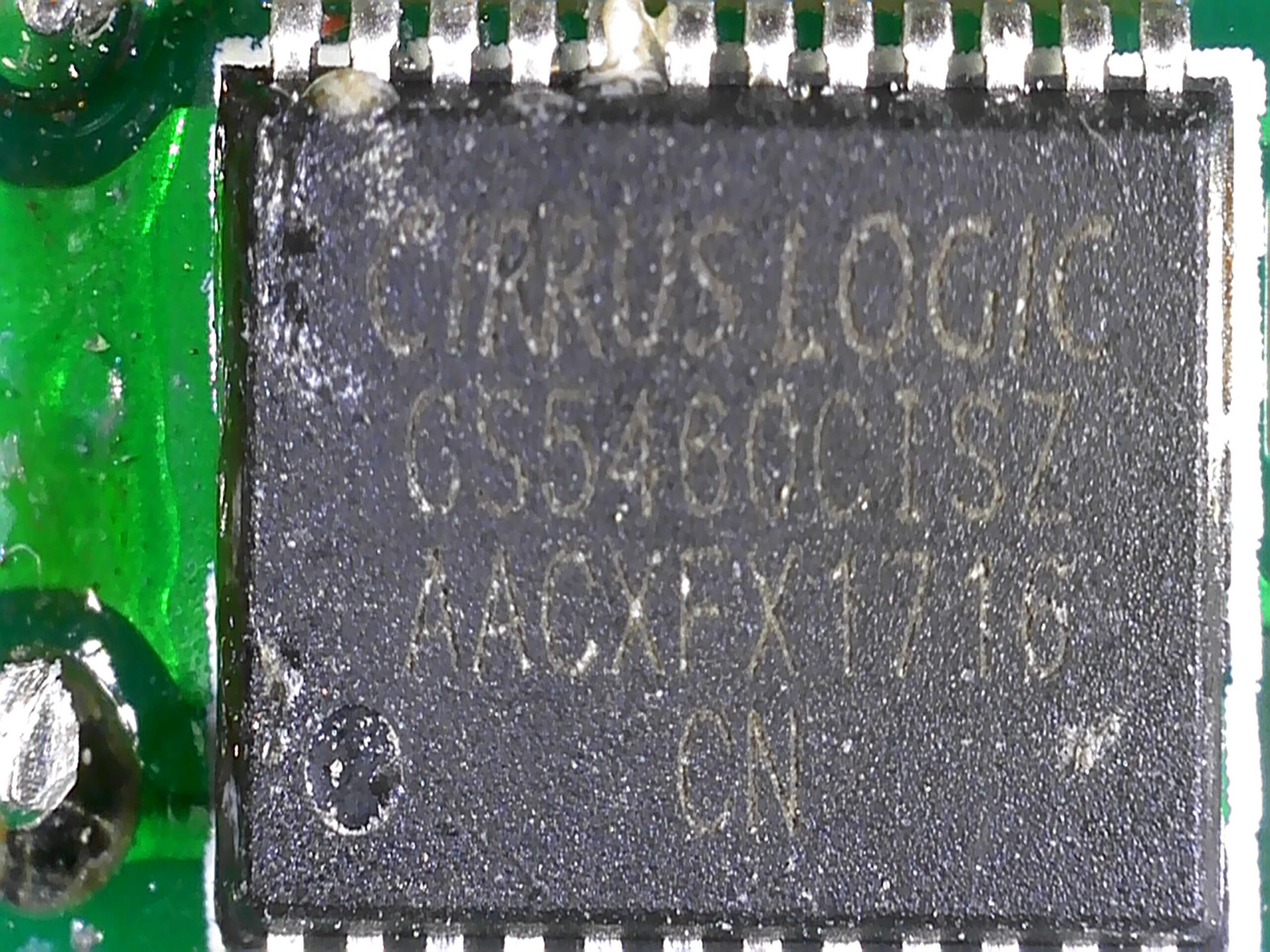
The big chip on the left side is a dedicated and very sophisticated power IC developed for energy meters (CS5460C-ISZ by Cirrus Logic). It has many functions onboard and requires relatively little external circuitry. Things like a shunt resistor or voltage dividers for the mains voltage, filters and adequate voltage supply circuits are still required.
On the right another IC can be found (U4) which is an EEPROM chip with I2C interface required for startup and operation of the CS5460C-ISZ.
Speaking of supply circuit, roughly in the middle of the PCB (U1), a linear regulator IC is located (CJ78L05). So somewhere the AC mains voltage must have already been converted to DC (at least to some extent).
Now the 0.33uF 275V film capacitor and the 150 Ohm resistor located on the other side of the PCB together with the diodes on the input side of U1 looks suspiciously like some variant of a capacitive voltage dropper circuit. A quick look into the datasheet reinforces this assumption.
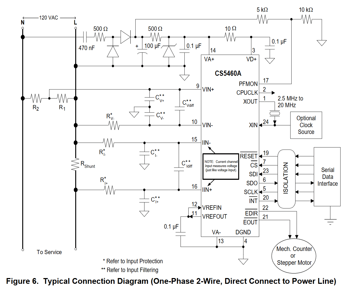
In the top left the 470nF in series to the 500 Ohm provide high impedance for the AC voltage (few kOhms), it then gets half-wave rectified, then smoothed by an electrolytic capacitor which is connected in parallel to a zener diode most likely in the range of 4.7V since VA+ and VD+ require between -0.3 and +6V. The whole circuit is hot, it has a far higher voltage to ground potential than the voltage at the output suggests. Also, only very little current can be drawn due to the high impedance in connected in series.
Furthermore, a voltage divider as well as a shunt resistor next to some filtering can be spotted.
The schematic displayed here is not exactly the same as on the board since there is a linear voltage regulator soldered. Maybe it was cheaper than a TVS or more current was required. The output then supplies the main IC, the EEPROM chip and the driver IC for the display.
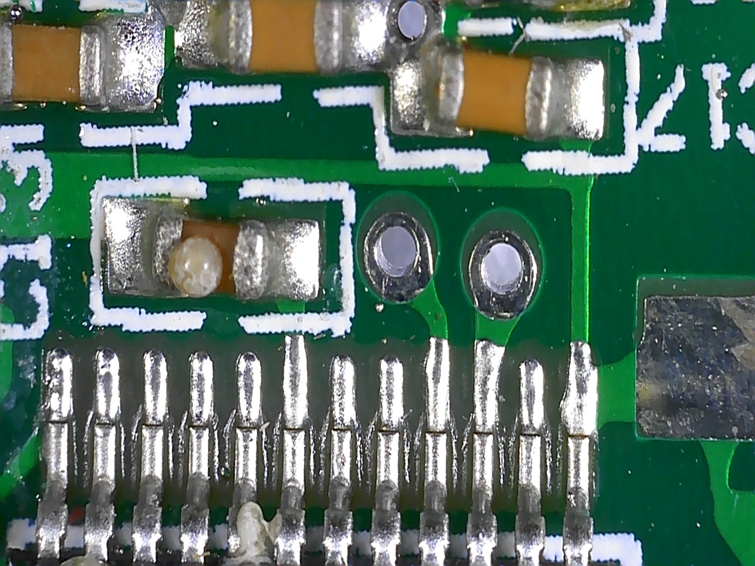
The shunt resistor for current measurement is connected to pin 15 and 16, their trace is led to the back of the PCB through vias.
Conclusion
Besides the broken ribbon cable (happened when I opened the case, so that’s on me) I didn’t see any obvious faults on why the display most of the time showed approximately double the current value, even at exclusively ohmic loads.